NVIDIA Carter
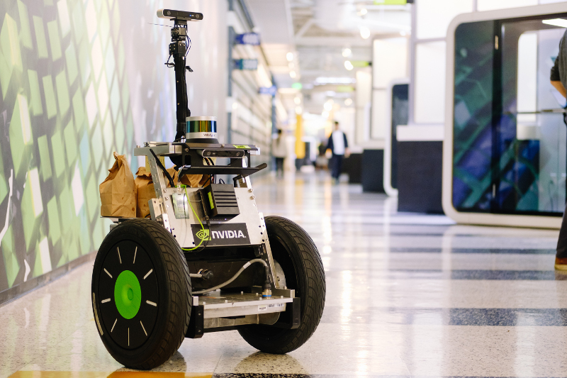
Carter is a robot developed as a platform to demonstrate the autonomous navigation capabilities of the Isaac SDK. It is based on a differential drive and uses LIDAR and a camera to perceive the world.
This document walks you through hardware assembly and software setup for Carter.
Parts
The following components are required to build the Carter hardware platform:
Devices
| Part | Qty |
|---|---|
| Jetson AGX Xavier Developer Kit | 1 |
| Segway RMP 210 | 1 |
| Segway RMP E-Stop (included with Segway RMP 210) | 1 |
| Network switch: Netgear 8-Port (GS108) or Netgear 5-Port (GS105) | 1 |
| USB hub (powered): StarTech ST7300USBME | 1 |
| WiFi card: Intel 8265NGW | 1 |
| WiFi antennas (pair, M.2): CHAOHANG 6484109 | 1 |
Sensors
| Part | Qty |
|---|---|
| ZED Camera | 1 |
| Velodyne VLP-16 lidar | 1 |
| Intel RealSense Depth Camera D435 | 1 |
| Bosch BMI160 IMU | 1 |
Power/Control
| Part | Qty |
|---|---|
| Power distribution block: McMaster-Carr 7527K44 | 2 |
| Spade connectors | 10 |
| Blade contact | 4 |
| Blade housing - black | 2 |
| Blade housing - red | 2 |
| Bluetooth Controller: NVIDIA SHIELD or DualShock 4 | 1 |
Hardware – Custom Parts
Hardware – Standard Parts
| Part | Qty |
|---|---|
| M8x40 socket head screw | 4 |
| M8x30 socket head screw | 8 |
| M8x12 or M8x20 socket head screw | 16 |
| M8 locknut | 2 |
| M6x20 SOC or button head screw | 2 |
| M6 hex nut | 2 |
| M5x20 SOC or button head screw | 1 |
| M5 locknut | 1 |
| M3x35 socket head screw | 4 |
| M3 washer | 4 |
| M2x6 screw | 2 |
| 1/4”-20x1” socket head screw | 2 |
| Dowel pins: 4mm or 5/32” | 2 |
| 2x20 Connector Housing | 1 |
| 6-pin 0.1” connector housing w/ latch | 1 |
| 6-pin connector header through hole | 1 |
| Socket contact gold 22-24 AWG crimp | 8 |
Cables and Wiring
| Part | Qty |
|---|---|
| 2.5mm barrel plug (for Jetson AGX Xavier) | 1 |
| 2.1mm barrel plug (for Ethernet switch and lidar) | 2 |
| Ethernet cable (Cat 5e or better) | 2 |
| 18 Gauge Wire (various lengths) |
Host Machine Requirements
You will need a Linux host machine to deploy applications to Carter. System requirements for this host machine are described in the System Requirements section of the SDK Manager documentation.
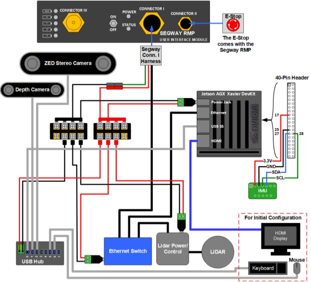
Carter Wiring Diagram
The following diagram shows the wiring for Carter. It may be useful to reference this diagram during assembly.
Assembly Instructions
Follow these steps to assemble Carter:
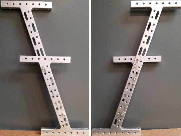
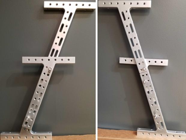
1. Assemble T Brackets into Legs
Carter has two legs that connect to the Segway RMP. Each leg consists of three T brackets and five M8x30 screws.
For each leg, secure three T brackets together using two screws on the inner side and three screws on the outer side, arranged as shown in the image below.
The two legs should be mirrored after assembly.
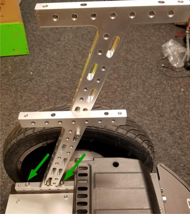
2. Attach Legs to RMP
Secure each leg to the Segway RMP platform using two M8x40 screws in the inner holes of the bottom bracket. The image below shows the right leg.
3. Attach Terminal Blocks and Wiring to Xavier Plate
A small mount plate will serve as the mount plate for the Jetson AGX Xavier board.
Important
The small mount plate has a set of four holes that are smaller than the rest of the holes. For these instructions, the edge of the plate that is closer to these holes is referred to as the “top” edge of the plate.
Attach the two power distribution blocks to the top half of the plate using sticky-back hook-and-loop strips. These blocks break out power from the 12V RMP battery to other devices in the system. The RMP wiring harness uses 18-gauge wires. We recommend using 18-gauge wires with crimped-spade connectors for terminal blocks to these devices:
- The 2.5mm barrel plug for Xavier, with positive on the inner contact
- The removable connector to the Power1+ and Power1- wires on the RMP CONNECTOR I Breakout Harness, which supplies 12V from the RMP battery
- The 2.1mm barrel plug for the GS108 or GS105 Ethernet switch
- The 2.1mm barrel plug for the VLP-16 lidar
- The power terminal for the Startech USB hub
Note
All devices outlined in the Parts section can accept 12V input. If you substitute other devices for those in the parts list, you may need to use additional step up/down regulators. You can also purchase regulators from Segway to expand the auxiliary power capacity of the RMP 210 beyond 150W and provide alternative voltage levels from the RMP CONNECTOR I Breakout Harness.
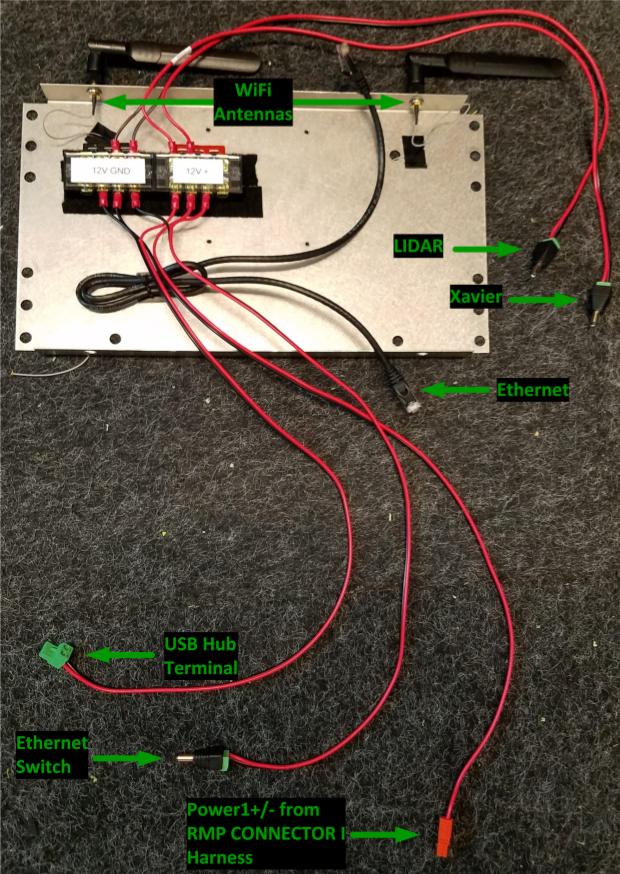
Screw the WiFi antennas into the two holes on the top flange of the plate. Feed the wiring through the two nearby large holes on the face of the plate. This will allow the wires to reach the Xavier board on the other side of the plate.
Attach the Ethernet cable to the plate. One end will be attached to the Xavier board and the other to the Ethernet switch. The connections will be made in a later step.
The image below shows the various connections from the power distribution blocks, the Ethernet cable, and WiFi antennas on the back of the Xavier plate.
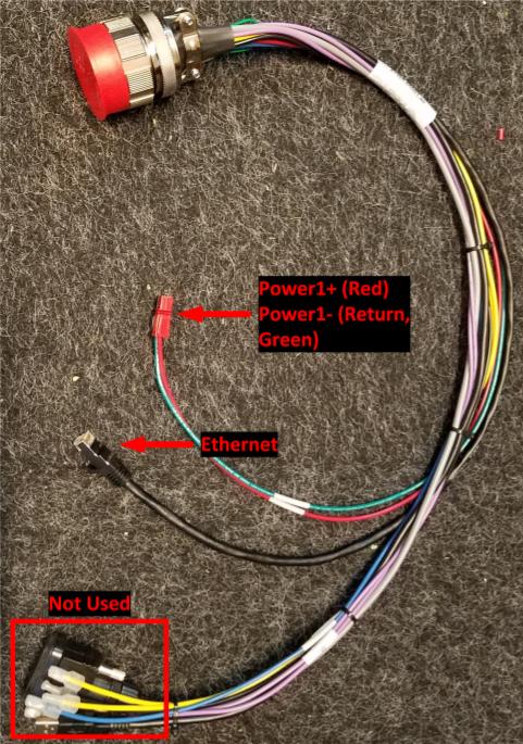
4. Prepare RMP CONNECTOR I Harness
Cut the factory crimps off of the Power1+ (red) and Power1- (Return, green) wires on the RMP CONNECTOR I harness. Add a mating removable connector to these wires for Power1 wiring to the power distribution blocks on the Xavier plate.
Note
You will only use the Power1+/Power1- wires and Ethernet cable on the RMP Connector I harness.
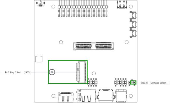
5. Prepare the Xavier board
Install the WiFi card in the J505 M.2 slot on the bottom of the Xavier board.
Verify that the jumper on the J514 Voltage Select shorts pins 1 and 2 (denoted by the small green box in the diagram below).
Position the Xavier plate near the Xavier board and attach the antenna cables to the WiFi card.
6. Attach the Xavier Board to the Xavier Plate
Remove the four screws shown below from the Xavier board.
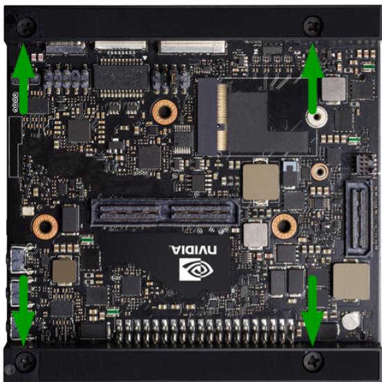
Leave the Xavier board upside down. Align the side of the Xavier board with the power jack and Ethernet and USB connectors, shown at the top of the image above, with the top edge of the Xavier Plate. With the Xavier Plate facing downward, lift the plate, place the M3 washers on the Xavier mounting holes, and insert the M3x35 screws.
Lower the plate onto the Xavier board. Ensure you are aligning the screws with the holes in the feet and avoiding the antenna wires. Secure the M3 screws to mount the Xavier board to the plate.
The photo below shows the face of the Xavier plate with the Xavier board mounted. Note the USB, Ethernet, and power connectors on the top edge and the unused PCIe connector on the left side.
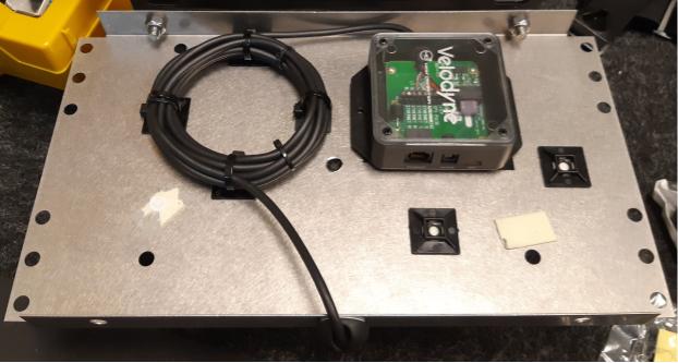
7. Attach Lidar and RealSense Camera to Mount and Plate
The other small mount plate carries the VLP-16 lidar. The 3D-printed lidar mount has two small holes on the top for the alignment dowels and a through hole in the center for securing the lidar with the 1/4”-20x1” bolt. The default orientation of the lidar is pointing away from the caster (i.e. the small third wheel) of the RMP, with the USB cable on the back pointed toward the caster. Secure the lidar mount to the small mount plate with two M8x30 screws and M8 locknuts.
Use two M2x6 screws to secure the Realsense Depth Camera to its mount. This mount attaches to the front portion of the lidar mount with a M6x20 screw and nut. The mount angle should be set to 0 degrees by default, and can be adjusted in 15 degree steps. Plug the Type C end of a USB Type C to Type A cable into the RealSense camera.
Secure the lidar wiring and components to the bottom of the lidar Plate.
Note
This mount places the RealSense camera in the following location relative to the robot
base: "translation": [0.150, 0, 0.573]. See the Setting up Software on Carter
section for more information on capturing translation in the Carter JSON configuration.
Important
Mounting the lidar and depth camera in this step, the stereo camera in step 9, or the IMU in step 14 differently than instructed will cause unexpected behavior with the default software. If there are any discrepancies, you will need to update the JSON configuration for Carter. Refer to the Setting up Software on Carter section for further information.
8. Attach Lidar Plate to Carter
Use four M8x12 or M8x20 screws in the corners to secure the lidar plate to the middle T bracket, as shown in the photo below. Connect one end of an Ethernet cable to the lidar. The connections to the Ethernet switch and power will be made in a later step.
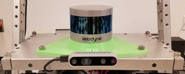
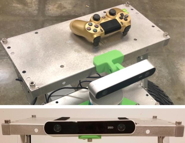
9. Connect ZED Camera to Camera Plate
Attach the ZED camera to the stereo camera mount and connect that piece to the stereo camera plate mount. Use double-stick tape to attach the stereo camera plate mount to the large mounting plate (camera plate). The mount angle should be set to 0 degrees (horizontal) by default and can be adjusted in 15 degree steps.
Secure the camera plate to the top T bracket with four M8x12 or M8x20 screws in the corners.
Note
This mount places the left lens of the ZED camera in the following location relative to
the robot base: "translation": [0.098, 0.06, 0.763]. See the Setting up Software on Carter
section for more information on capturing translation in the Carter JSON configuration.
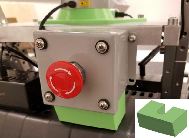
10. Attach E-Stop button
Use double-stick tape to attach the E-Stop mount bracket to the side of the RMP E-Stop Button housing that contains the cable. Route the cable through the cut-out in the mount bracket.
Note
You can also use hook and loop fastners to secure the E-Stop mount bracket to the RMP battery cover on which it rests.
Use a M5x20 screw and M5 locknut to secure the top right of the E-Stop Button housing to the lidar plate.
Connect the E-Stop cable to CONNECTOR II on the RMP Centralized Control Unit (CCU). Secure the cable so that it doesn’t interfere with the wheels.
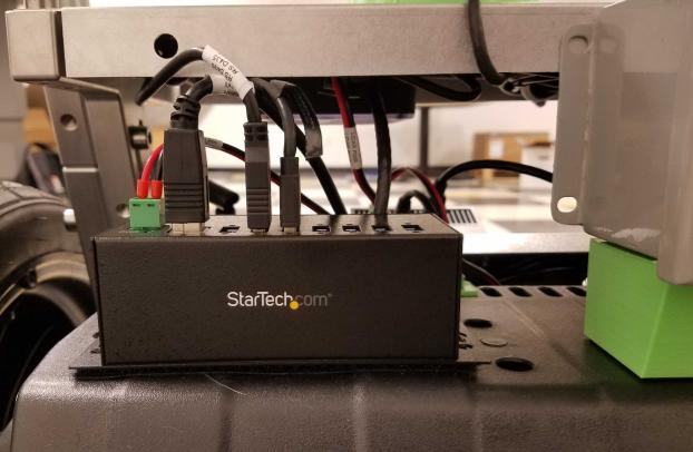
11. Attach USB Hub to RMP Battery
Use hook and loop fasteners to attach the USB hub to the RMP battery cover. The USB hub should be located to the left of the E-Stop. This location will make it easier to connect devices for development and debugging in the future.
The photo below shows the hub after all connections are made, but you don’t need to connect anything in this step.
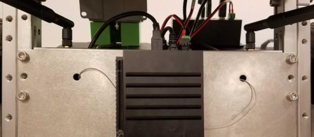
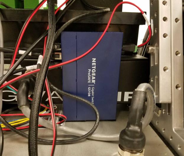
12. Attach Ethernet Switch to Front of RMP CCU
Use hook and loop fasteners on the bottom of the Ethernet switch to attach it vertically to the front right of the CCU, with the Ethernet ports facing to the left. Leave enough room for the barrel plug to connect on the right side.
The photo below shows the Ethernet switch after all connections are made, but you don’t need to connect anything in this step.
13. Make Connections on the Xavier Plate
Route the cabling from the RMP harness below the CCU to the Xavier plate. The Ethernet cable and power1+/power1- wires (12V source) are the only connections that you need to make.
Move the Xavier plate close to the front of Carter and make these connections from the back of the Xavier plate:
- power1+/power1- wires from power distribution block to RMP CONNECTOR I harness
- 2.1mm barrel plug from power distribution block to Ethernet switch
- 2.1mm barrel plug from power distribution block to lidar
- Power terminal from power distribution block to the USB hub
- USB cable from USB hub (Type B end), routed toward the Xavier Plate
Tip
At this point, you may find it more convenient to perform steps 2-3 in the Setting up Software on Carter section (i.e configuring the IP addresses of the lidar and RMP 210) because all the components and connections are easily accessible. If you do so, you will need to use the Linux host machine, rather than the Xavier, to connect to and configure these devices as described.
14. Set up IMU
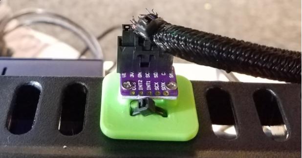
Add 6-pin sockets or headers to the VIN, 3V3, GND, SCL, and SDA signals on the BM160 board.
Secure the BMI160 board to the IMU mount with two M2x6 screws, with the socket oriented as shown below.
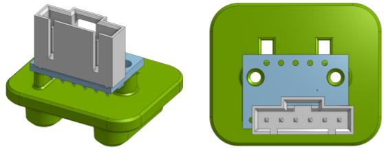
Depending on the resolution of the 3D printer, the mounting holes may need to be drilled to allow the screws to fit. The two cutouts in the mount next to the board allow you to use a zip tie to secure the mount to the RMP battery cover.
| BMI 160 | Jetson AGX J30 40-pin | ||
|---|---|---|---|
| Pin | Signal | Pin | Signal |
| 1 | VIN | NC | |
| 2 | 3V3 | 17 | 3V3 |
| 3 | GND | 25 | GND |
| 4 | SCL | 28 | I2C_GP2_CLK_3V3 |
| 5 | SDA | 27 | ISC_GP2_DAT_3V3 |
| 6 | CS | NC | |
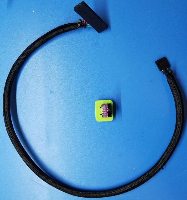
Use jumper wires or create a cable to connect the 3V3, GND, SCL, and SDA pins of the BMI 160 to the Xavier J30 40-pin connector. If you are using a 40-pin socket for the Xavier side, take care to note the location of pin 1. The photo below shows an example cable harness for the IMU:
The bottom of the 3D-printed mount has two tabs that insert into two vent holes on top of the RMP battery cover. It should be installed in the two center holes with the connector side closer to the edge of the cover and secured with a zip tie, as shown in the photo below, which was taken from the rear of the RMP.
Route the Xavier side of the IMU cable to the bottom of the RMP platform. It will curl under the Xavier plate to make its connection.
15. Make Final Connections
Make the following connections:
- USB cable (Type A end) to Xavier
- Ethernet cable from the back of the Xavier plate to Xavier
- 2.5mm barrel plug to Xavier jack
- Ethernet from lidar to Ethernet switch
- Ethernet from RMP CONNECTOR I harness to Ethernet switch
- One end of the Ethernet cable on the Xavier Plate to the Ethernet switch
- ZED Camera USB to USB Hub
- RealSense camera USB to USB Hub
Tip
To make future debugging easier, add labels with device names to all cables connected to the USB hub and Ethernet switch.
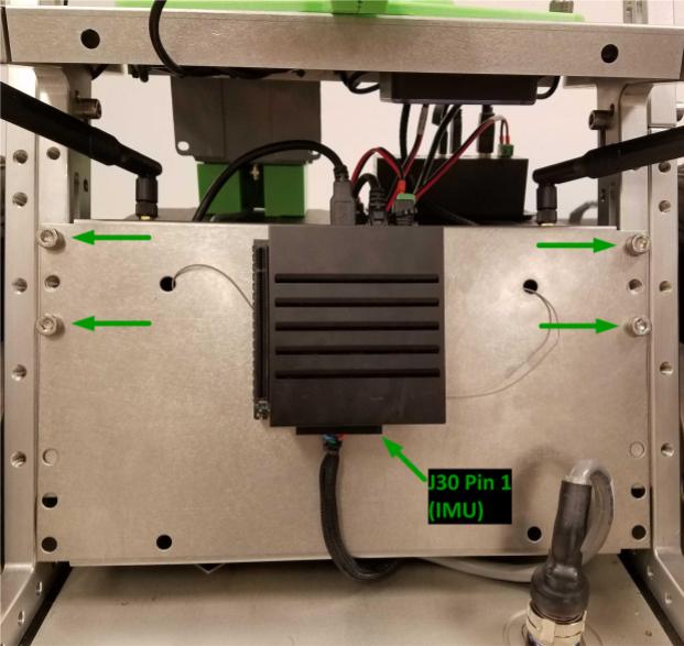
16. Attach Xavier Plate and IMU
Use four M8x12 or M8x20 screws to secure the Xavier plate to the lowest bracket of each leg. Attach the IMU 40-pin connector to the Xavier board. Pin 1 of the connector is on the right when facing the Xavier board.
17. Secure Cables
Use zip ties to secure the USB cables for the Realsense and ZED camera–and any other loose cables as needed.
Setting up Software on Carter
After you assemble Carter, go through the following steps to configure the software on it.
Note
All commands should be executed from the host development workstation, unless the instructions state to run them from the Jetson AGX Xavier.
1. Configure the Jetson AGX Xavier
- Install the Jetson operating system on the Jetson AGX Xavier as described in the SDK Manager documentation.
- Obtain the IP address of the robot as described in the Getting Started with Jetson Nano guide.
Tip
Alternatively, you can configure your wireless network to assign a static IP address to Carter. Consult your network administrator for proper implementation.
- Follow the Setup guide to install Isaac SDK, along with all of its dependencies, on the Xavier.
- Follow the steps in the Deploying and Running on Jetson section of the Getting Started document to register your SSH key with the Xavier.
2. Configure the VLP-16 Lidar
Out of the box, the VLP-16 lidar is configured with an IP address of 192.168.1.201. You will need to change this address:
Set the Jetson AGX Network to 192.168.1.5.
Use a web browser to navigate to http://192.168.1.201. This should open the configuration page for the VLP-16 lidar.
- Change the Host (Destination) IP address from “255.255.255.255” to “192.168.0.5” (i.e. the IP address of the Xavier) and click the Set button. Note that each section has its own Set button.
- Change the IP address of the Network (Sensor) (i.e. the Lidar itself) to “192.168.0.201” and click the Set button.
- Click the Save Configuration button.
Change the Jetson AGX Network back to 192.168.0.5.
Ping the VLP-16 lidar from the Xavier to confirm the new configuration:
$ ping 192.168.0.201If the ping fails, refer to Appendix J - Network Configuration in the VLP-16 User Manual for help.
3. Configure the RMP 210
Out of the box, the RMP 210 has a default IP address of 192.168.0.40. Ping the RMP 210 from the Xavier to confirm these devices can see each other:
$ ping 192.168.0.40
4. Configure the Xavier
Connect the Jetson AGX Xavier to a display and connect a keyboard and mouse to the USB hub.
Log in to the Xavier.
Connect to a strong WiFi network.
Install dependencies on the Xavier:
Install “ssh” on the Xavier:
sudo apt-get install ssh
Install “jstest-gtk” on the Xavier. This is required to configure and calibrate the joystick controller.
sudo apt-get install jstest-gtk
Set the controller to pairing mode (refer to the controller manual for instructions). From Bluetooth Settings, pair and connect the joystick.
Set up the RealSense camera:
Configure the RealSense camera codelet as described on the RealSense Camera page.
From the host machine, deploy the sample application to verify that the RealSense camera is working:
./engine/build/deploy.sh --remote_user <username_on_robot> -p //apps/samples/realsense_camera:realsense_camera-pkg -d jetpack43 -h <robot_ip>
Where
<username_on_robot>is your username on the Xavier and<robot_ip>is the IP address of the Xavier.Log in to the Xavier from the host machine using SSH and run the sample application as follows:
cd deploy/user_name/realsense_camera
./apps/samples/realsense_camera/realsense_camera
On the host machine, navigate to
http://<robot_ip>:3000/. Check the “realsense camera” channel to verify that the camera is running.
.._RealSense Camera :https://docs.nvidia.com/isaac/isaac/packages/sensors/doc/realsensecamera.html
Configure the ZED camera as described in the ZED Camera document.
On the Xavier, edit the sensor configuration files for Carter to accurately reflect the position of the sensors. The following are file locations and example configurations for the different sensors:
Tip
See the Other Issues section of the Frequently Asked Questions document for a description of 3D pose values.
Lidar:
isaac/apps/carter/robots/"2d_carter.carter_hardware.vlp16": { "lidar_initializer": { "lhs_frame": "robot", "rhs_frame": "lidar", "pose": [1.0, 0.0, 0.0, 0.0, 0.022, 0.0, 0.625] } }RealSense camera:
isaac/apps/samples/realsense_camera"2d_carter.carter_hardware.camera": { "realsense_pose": { "lhs_frame": "robot", "rhs_frame": "camera", "pose": [0.5, -0.5, 0.5, -0.5, 0.150, 0, 0.573] }Tip
Refer to the RealSense Camera document for more information on using the RealSense camera with Isaac applications.
ZED camera:
isaac/apps/samples/follow_me"camera": { "zed_left_camera_initializer": { "lhs_frame": "robot", "rhs_frame": "left_camera", "pose": [0.5, -0.5, 0.5, -0.5, 0.098, 0.06, 0.763] }Tip
Refer to the ZED Camera document for more information on using the ZED camera with Isaac applications.
Creating a Map for Carter
Follow the steps below to create a map and configure it for the Carter application:
- Set up the Isaac SDK on your host machine as described on the Setup page.
- From the Isaac SDK repository on your host machine, deploy either the GMapping or the Cartographer application to Carter.
- Use the Map Editor to create waypoints and restricted areas on your map.
- Create a config and graph file for the map. Refer to the sample files at
isaac/apps/assets/maps.
Running Isaac Applications on Carter
This section describes how to run four different sample applications on Carter.
Application 1: Random
This application instructs Carter to travel from one waypoint to another using randomly chosen waypoints.
From the host machine, deploy the Carter application to the robot:
./engine/build/deploy.sh -p //apps/carter:carter-pkg -d jetpack43 -h <robot_ip> --remote_user <username_on_robot> -s
SSH into the robot (using the Xavier IP).
Go to the
/deploy/<host_username>/carter-pkgdirectory.Run the application:
./apps/carter/carter -m <map_name>
To create a map of large environments, you need to tune the map to create a dense graph. This will speed up path planning for the robot. Refer to the Global Planner section of the Tuning the Navigation Stack document for more details.
Go to the Isaac Websight visualization tool (https://<robot_ip>:3000) to visualize the application.
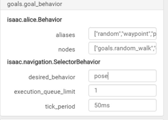
Switch to a different goal behavior in Websight:
- Go to the “goals.goal_behavior” node.
- Change the “desired_behavior” from “Random” to “WayPoint”, “Pose”, “Route” etc.
- Go to “goals.pose_as_goal”, “goals.waypoint_as_goal”, or “goals.patrol” and click Submit to activate the application with that configuration.
Application 2: Waypoint
This application moves Carter to a given goal using the isaac.navigation.MapWaypointAsGoal component.
To use the Waypoint application, add the sample Flatsim delivery application to your
Carter application. This sample application is located at isaac/apps/carter/carter_delivery/carter_delivery_flatsim.app.json.
Application 3: Pose
This application moves Carter to a given goal in Websight.
The “pose_as_goal” config is part of the “goal_generators.subgraph.json” file by default. Follow these steps to enable this application:
- Open Websight.
- Under “goals.goal_behavior”, change the “desired_behavior” to “pose_as_goal”.
- Add the “pose_as_goal” marker to navigate the robot using the pose.
Refer to the Additional Notes section of the Interactive Markers document for more details.
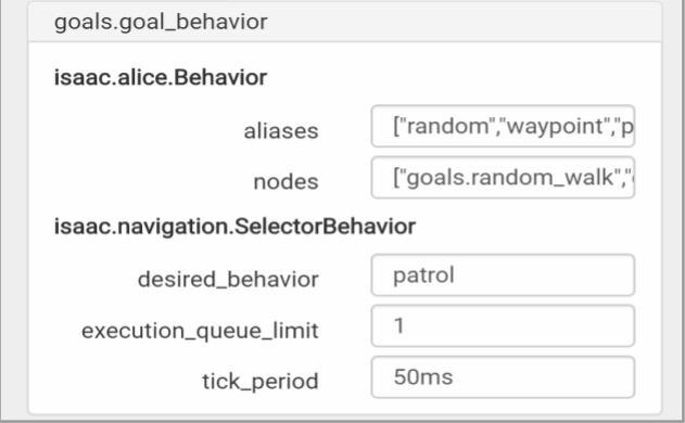
Application 4: Patrol
This application instructs Carter to patrol along a pre-defined route.
First, modify the config for “patrol” mode in isaac/packages/navigation/apps/goal_generators.subgraph.json:
Add a “route” and list the waypoints on the patrol route.
"patrol": {
      "isaac.navigation.Patrol": {
         "tick_period": "250ms",
         "route": [
            "home",
            "kitchen",
            "office"
         ]
      }
   }
After adding the route to the sample JSON, run the Carter application and open Websight. Under the “goals.goal_behavior” configuration, change the “desired_behavior” to “patrol”.
Troubleshooting
RMP 210 does not move
Ensure the RMP 210 has the correct IP address (192.168.0.40) and you are able to ping that address from the Xavier. If the RMP 210 cannot connect to its host, it will power down automatically after a timeout.
VLP-16 lidar does not connect Ensure the lidar has been programmed with the correct IP addresses: 192.168.0.201 for itself and 192.168.0.5 for the host/Xavier. Ping the VLP-16 from the Xavier to ensure the connection is working.
Isaac application cannot access the IMU
Check the continuity of the cable from the Xavier to the pins on the IMU board.
USB hub is not working
Check the power- and ground-wire mapping and continuity to the terminal.
RealSense camera not working
Ensure that the StarTech USB hub is externally powered and that you are using properly rated USB 3.1 cables. Double-check that any issues can be reproduced with the RealSense camera connected directly to the Xavier using its original USB cable.
Wires are coming loose
Use ferrules to attach wires to the barrel plugs and USB hub power terminal. They make for a more secure connection than bare wire.